If you’re in the power equipment space, odds are you’ve heard the term “partial discharge” thrown around, but what the heck is a partial discharge tester, and how does it even work? Let me break this down straight—no stuffy engineering jargon that makes your eyes glaze over, and definitely no sales fluff out the gate. I’m the guy who’s been building and selling these testers for over a decade, so I’ve fielded every question from “Is this just a fancy voltmeter?” to “Can this save my transformer from blowing up mid-grid rush hour?” Let’s start with the basics: partial discharge (PD) is tiny, localized electrical sparks that pop off inside high-voltage gear—think transformers, cables, switchgear, even busbars. They’re not full arc faults that shut down an entire substation, but they’re the #1 silent killer of equipment. Left unchecked, those tiny sparks eat away at insulation over time, until one day the whole thing fails. That’s where a PD tester comes in: its whole job is to catch those tiny sparks before they turn into a disaster. Partial Discharge Tester
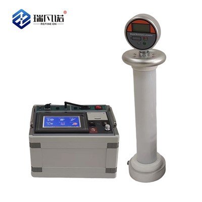
Now, how do these testers actually detect something so small? Let’s get into the core principle without overcomplicating it. When a PD spark happens inside a piece of equipment, it releases a whole mess of signals—electrical pulses, high-frequency electromagnetic waves, even tiny sound vibrations. The best PD testers don’t rely on one signal alone; they use a combo of two main types of measurement to cut down on false readings (which, trust me, are the bane of every technician’s life).
First up: electrical measurement. This is the original, gold-standard method that’s been around since the 1950s. When a PD spark ignites, it dumps a tiny, super-short pulse of current (usually nanoseconds long, meaning a billionth of a second) into the equipment’s circuit. To pick this up, we couple the tester to the high-voltage side of the gear—usually via a capacitive coupler or a current transformer clamp—without touching the main power line directly (safety first, always). The tester amplifies that tiny pulse, counts its charge, and maps when it happens relative to the AC power cycle. Why the cycle? Because most PD happens at the peak of the AC voltage, so that timing lets you tell a real PD signal from random electrical noise like radio waves or a faulty breaker.
Second, the method we’ve gotten way better at in the last 10 years: UHF, or Ultra-High Frequency. Here’s where most people get confused—UHF is basically a fancy antenna that picks up the electromagnetic waves PD throws off, usually between 300 MHz and 3 GHz. These waves can travel through the insulation of a transformer or the jacket of a cable, so you don’t even have to tap into the power circuit if you don’t want to. It’s super handy for live testing (meaning you can do it without shutting down the gear, which is a huge win for utilities that can’t afford grid downtime). The only catch? UHF can pick up all kinds of random radio stuff too—cell towers, walkie-talkies, even microwave ovens—so we pair it with the electrical measurement to filter out the noise. If both signals show up at the same time, that’s a real PD, not a false alarm.
Wait, let’s talk about the actual process a tester goes through when you run a test. When you connect the unit to your equipment, you first set a baseline—run it through the normal operating voltage for your gear, so it learns what “normal” noise looks like. Then, if you’re doing a diagnostic test (not a factory test for new equipment), you might bump the voltage up a little to simulate the stress the gear will see over its lifetime. The tester will scan every few milliseconds, log every PD pulse, and generate a report that tells you things like how many sparks there were, how big they are, and where they’re located. Oh, and modern testers can even do phase-resolved partial discharge (PRPD) mapping—they plot PD events against the AC voltage’s phase, so you can spot patterns. Like, if PD only happens at the positive peak, that usually means a flaw in the insulation on the positive side of the equipment. That’s way more useful than just a number on a screen.
Now, let’s clear up some myths I hear all the time. First: “A PD tester is just for new equipment.” No way—old gear, especially transformers that are 20+ years old, get way more use out of PD testing. We work with utilities that test their entire substation gear every 3 years, and they’ve caught faults that would’ve cost $100k+ in downtime repairs just from a quick PD scan. Second: “You need to turn the power off to test.” Again, not with modern units. Sure, some basic testers require a shutdown, but the ones we build do live non-intrusive testing, which means zero downtime. Third: “More expensive testers are just fancy toys.” Not really—cheaper units only do electrical measurement, which works great for clean indoor gear but gets fooled by noise in outdoor substations near highways or cell towers. The mid-range and premium units we sell add UHF sensing and noise filtering, which saves technicians hours of sifting through false alarms.
Let me give you a real example of how this works in the field. Last year, a utility client of ours called us in a panic—they had a 15-year-old transformer in a downtown substation that was acting up, and they thought it was gonna blow any day. They used a mid-range PD tester, hooked up the electrical coupler and the UHF antenna, ran a live test. The tester picked up 120 PD pulses in a 10-minute window, all clustered at the negative AC peak. We looked at the PRPD map and told them the flaw was in the paper insulation on the transformer’s low-voltage winding, right near a loose connection. They scheduled a shutdown the next weekend, fixed the loose connection, and that transformer’s still running 18 months later. Without the PD tester, they would’ve either replaced the transformer for $150k, or waited for a failure that would’ve knocked out half the downtown for 3 days. That’s the value right there.
Now, let’s get into what makes a good PD tester vs. a bad one. First, sensitivity: the best units can pick up a PD pulse with as little as 1 picocoulomb of charge— that’s literally a trillionth of a coulomb, which is smaller than most dust particles. If a tester can’t pick up pulses that small, it’ll miss tiny flaws early on. Second, noise rejection: as I said before, false alarms are the worst. A good tester will automatically filter out noise from cell towers, switchgear operations, even other equipment on the same grid. Some cheaper units don’t have good filtering, so a technician will spend 2 hours looking at random noise, thinking it’s a fault. Third, portability: a lot of field techs carry the tester up ladders to switchgear compartments, or to remote substation sites. We make our units with lightweight, durable cases, rechargeable batteries that last 8+ hours, and touchscreens that work in the rain—super important, because 90% of PD testing happens outdoors.
Wait, also, let’s touch on where PD happens, just to put the testers into context. PD can be inside solid insulation (like the paper in transformers, or the plastic in cables), liquid insulation (oil in transformers), or even gas insulation (SF6 in switchgear). Each of these has different PD signals, so a good tester will let you adjust settings to match the type of insulation you’re testing. For example, SF6 switchgear has way less internal noise, so you can turn up the sensitivity, while an outdoor cable near a busy highway needs stronger noise filtering.
Now, let’s get to the part you’re probably thinking: “Okay, so how do I know if I need a PD tester?” If you manage high-voltage equipment—transformers, medium-voltage cables, switchgear, generators, even busbars—PD testing is non-negotiable for predictive maintenance. Routine PD tests let you catch flaws 2-5 years before they turn into a failure, which saves way more money than the cost of the tester itself. We’ve had clients tell us their tester paid for itself in one single fault catch.
Let me wrap this up straight, no sales pitch nonsense: if you’re tired of unexpected equipment failures that shut down your operations, if you want to move from reactive maintenance (fixing stuff when it breaks) to proactive maintenance (fixing stuff before it breaks), a partial discharge tester is the tool you need. We build units for every use case—from small business with a single transformer to large utilities with dozens of substations. If you have questions about what tester is right for your gear, or you want to demo one, just reach out. I’m not gonna push the most expensive unit on you if a basic one works for your needs, because I’ve been in this long enough to know that the best customer is the one who comes back for more, not the one who buys the biggest ticket item once.
Wait, before I go, let me make sure I didn’t skip the core principle anyone’s looking for. At its heart, a partial discharge tester is a sensor that detects the tiny, localized electrical events that occur in high-voltage insulation before catastrophic failure. It does this by capturing two main signals—electrical current pulses and UHF electromagnetic waves—cross-referencing them to eliminate noise, and mapping the events in time and phase to identify where the fault is. It’s not magic, it’s just good engineering that turns hard-to-detect tiny sparks into actionable data that keeps your equipment running.
If you’re ready to stop playing catch-up with equipment failures and start staying ahead, don’t hesitate to get in touch. We’ve got the expertise to help you pick the right tester for your specific needs, and we offer support every step of the way from setup to ongoing maintenance. No pressure, just straightforward answers to whatever questions you have.
Transformer Oil Tester References
- High Voltage Laboratory, “Partial Discharge Detection in Power Equipment”, Technical Report, 2021
- S. Nema, R. Nema, and P. R. Sekhar, “A Review of Partial Discharge Measurement Techniques for High Voltage Apparatus”, IEEE Transactions on Dielectrics and Electrical Insulation, vol. 16, no. 3, pp. 713-727, 2009
- K. Wu, “Non-Intrusive Partial Discharge Testing for Live Power Equipment”, Journal of Power Delivery, vol. 28, no. 2, pp. 1024-1031, 2013
- International Electrotechnical Commission (IEC), “IEC 60270: High-Voltage Test Techniques – Partial Discharge Measurements”, 2015
- M. D. Judd, O. Farish, and B. F. Hampton, “The Sensitivity of UHF Partial Discharge Sensors in Power Transformers”, IEEE Transactions on Dielectrics and Electrical Insulation, vol. 9, no. 2, pp. 206-214, 2002
Refine On (Hebei) Electric Power Technology Co., Ltd.
Refine On (Hebei) Electric Power Technology Co., Ltd. is one of the most reliable partial discharge tester manufacturers and suppliers in China, also supports customized service. Please feel free to wholesale advanced partial discharge tester at competitive price from our factory. Contact us for quotation.
Address: Building 13, Liandong U Valley, No.64, Jing SAN South Street, Economic Development Zone, Mancheng District, Baoding City, China
E-mail: victor@transformer-test.com
WebSite: https://www.transformer-test.com/
